The electronic sensors, controllers and actuators or valves used to control a hydraulic system enable cranes, presses, injection molding machines, earth moving equipment and other heavy duty areas to operate faster and more accurately. The service, maintenance and installation of these electro-hydraulic systems require measurement tools that provide insight into the system circuit behavior.
Hydraulic system principles
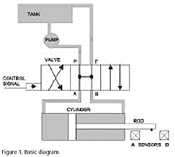
An hydraulic system has a fluid reservoir and a pump that pumps hydraulic fluid into the various hydraulic cylinders to create movement of the cylinder rod. A controller determines into which cylinder the fluid is pumped by opening a valve to that cylinder. The amount the valve is opened determines the speed of movement of the cylinder rod. The valve stays open and the rod moves until a sensor (or operator) feeds information back to the controller, causing it to close the valve. These feedback sensors are of three main kinds:
- limit sensors that feed back a position that has been reached, for example the end of stroke for the rod
- position sensors that feedback the actual position of the rod, for accurate positioning
- pressure valves that limit the maximum pressure by venting fluid to the reservoir
Measuring control and sensor signals
Control signals
The motion and speed of the cylinder rod are directly related to the oil flow regulated by the valve. Figure 1 shows a schematic drawing of a cylinder controlled by a 4-way proportional valve.
This valve has a P for pressure input that can be fed to either its A or B outputs depending upon the control signal, and an T for Tank (to fluid reservoir) return which is then connected to the non-pressurized A or B output. In this way the cylinder rod can be moved left or right by controlling the pressure fed to the A or B outputs with the control signal.
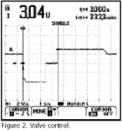 Figure 2 shows a valve control signal that has been measured using a ScopeMeter® test tool. Initially the signal has a level of +2 V. This means that the valve is slightly open, connecting the P to B (and A to T) and the cylinder rod is retracted.
When the voltage level changes to -4 V, the position of the valve changes and the flow direction of the oil is reversed (P to A and B to T), so the rod moves at high speed to the outermost position. After 2 seconds, the rod reaches its outermost position, the valve is closed (0 V) and the cylinder holds this position for about 1 second.
The voltage level then changes to +3 V to re-open the valve and retract the rod. Finally, just before the innermost position is reached again, the valve opening is reduced slowly by changing the voltage level from +3 V to +2 V, so the cylinder rod moves gently into its innermost position, where it is slowly forced to its mechanical limits.
Using the ScopeMeter test tool cursor function, it is easy to determine the time taken to move the cylinder rod from one position to the other, and to measure the control voltage levels during the various stages. From this picture, the engineer can see which changes he can make to adjust the behavior of the system. For instance: he could increase the retraction speed by increasing the control signal voltage from +3 V to +4 V, or he could reduce the retention force by decreasing the retention voltage level from +2 V to +1 V.
Sensor signals
Most systems use sensors to determine the position of various moving components, such as an "end-of-stroke" detector. Figure 2 illustrates how sensors can be used to detect a "cylinder rod" end-of stroke position.
The relatively low repetition rate of the rod movement requires a storage oscilloscope to store the measured signal characteristics over a long period of time. With the ScopeMeter test tool, signals from the sensors can easily be measured and stored.
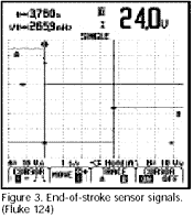 When the measurements are complete, the cursor function can be used to measure the time required for the rod to move from one sensor the other. Figure 3 shows the signals measured on sensor A and B. The left cursor is positioned on the falling edge of the sensor A signal. This is where the cylinder rod leaves the sensor A position. The right cursor is positioned on the rising edge of the sensor B signal. This is where the cylinder rod reached the sensor B position. The cursor read-out indicates the time duration (dt) between both cursor positions. When positioning information is required, a resistive linear displacement transducer is often used for short rod movements. These give an output signal directly related to position.
 For accurate positioning on long rod movements, servo cylinders are used. Here a sensor is mounted in the cylinder head, where it is protected from water, dirt and other environmental influences. The sensor operates by magnetically sensing a pattern of grooves cut into the base of the piston rod. The change in the magnetic field caused as the grooves pass the cylinder head generate a signal in the sensor, which is converted by separate electronics into a pulse. When the direction of the rod is reversed, a phase shift in the sensor signal output occurs enabling the direction of the rod to be determined.
By counting pulses, and with knowledge of the direction of travel, highly accurate rod positioning can be realized.
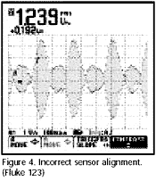
 During initial installation of the system, or if any of the sensors have to be replaced when carrying out maintenance, the sensor output signals must be aligned to ensure that they are correctly processed by the systems electronics. In particular, the successive pulses in the output wave-train must be symmetrical and of equal amplitude. Figures 4 and 5 show incorrect and correct alignment of this sensor output.
Conclusion
To verify correct operation of electro-hydraulic systems, visual storage of the control signals over time is essential. The ScopeMeter 120 Series test tools low-speed signal display capabilities make these instruments ideal for measuring and analyzing hydraulic control signals, and their rugged battery powered capabilities enable them to work in all the environments where hydraulic systems are employed.


 Figure 2 shows a valve control signal that has been measured using a ScopeMeter® test tool. Initially the signal has a level of +2 V. This means that the valve is slightly open, connecting the P to B (and A to T) and the cylinder rod is retracted.
  When the measurements are complete, the cursor function can be used to measure the time required for the rod to move from one sensor the other. Figure 3 shows the signals measured on sensor A and B. The left cursor is positioned on the falling edge of the sensor A signal. This is where the cylinder rod leaves the sensor A position. The right cursor is positioned on the rising edge of the sensor B signal. This is where the cylinder rod reached the sensor B position. The cursor read-out indicates the time duration (dt) between both cursor positions. When positioning information is required, a resistive linear displacement transducer is often used for short rod movements. These give an output signal directly related to position.
 For accurate positioning on long rod movements, servo cylinders are used. Here a sensor is mounted in the cylinder head, where it is protected from water, dirt and other environmental influences. The sensor operates by magnetically sensing a pattern of grooves cut into the base of the piston rod. The change in the magnetic field caused as the grooves pass the cylinder head generate a signal in the sensor, which is converted by separate electronics into a pulse. When the direction of the rod is reversed, a phase shift in the sensor signal output occurs enabling the direction of the rod to be determined.
 During initial installation of the system, or if any of the sensors have to be replaced when carrying out maintenance, the sensor output signals must be aligned to ensure that they are correctly processed by the systems electronics. In particular, the successive pulses in the output wave-train must be symmetrical and of equal amplitude. Figures 4 and 5 show incorrect and correct alignment of this sensor output.